For solar inverter charging at the same battery voltage, 100A is five times 20A and 120A is six times 20A. With sufficient input power and a suitably rated battery bank, this higher current can charge proportionally more capacity within the same ideal constant-current time window.
Nexus Solar Energy confirms 100A-or-higher charging on supported INNO 9G and INNO 9G Pro models in its 3–15kW range. The exact maximum depends on the supplied model and power source. This guide explains what that capability means for battery-bank sizing and why the current label needs to be read with voltage, capacity and battery limits.
What a battery charging-current rating measures
Battery charging current is the current entering the bank. PV-input current belongs to the solar input, and AC-input current belongs to the grid/generator side. The voltages and conversion stages differ, so their ampere values cannot be exchanged directly.
An inverter can have separate solar, AC and combined charging limits. If a model’s combined limit is 120A, adding nominal source figures does not permit exceeding that combined limit. Use the model’s actual limits and the battery’s recommended charging current.
A worked example: two, ten and twelve batteries
For the following calculation only, assume identical 12V/200Ah batteries that are approved for the proposed bank, the same chemistry and temperature, and a 20% to 80% SOC window. The bank stays at nominal 24V. The table is an electrical illustration, not an installation wiring plan.
| Calculation | Reference | Five times the capacity | Six times the capacity |
|---|---|---|---|
| Battery arrangement for the calculation | 2 in series, 1 string | 2 in series, 5 parallel strings | 2 in series, 6 parallel strings |
| Total battery count | 2 | 10 | 12 |
| Nominal bank voltage | 24V | 24V | 24V |
| Bank capacity | 200Ah | 1,000Ah | 1,200Ah |
| Capacity added over 20–80% SOC | 120Ah | 600Ah | 720Ah |
| Total charging current | 20A | 100A | 120A |
| Ideal constant-current estimate | 6 hours | 6 hours | 6 hours |
The reference calculation is 120Ah ÷ 20A = 6 hours. The larger-bank calculation is 720Ah ÷ 120A = 6 hours. With equal current sharing, each of the six strings in the last example receives 20A. The total charger current is 120A; every battery does not individually receive 120A.
The larger bank stores more energy, and the source must supply more energy during the charging window. The higher current makes that charging rate possible; it does not create extra energy.
Why the real charging time can differ
The example assumes constant current for its calculation. Actual lead-acid and lithium charging is affected by the battery’s charging profile, voltage limits, taper/absorption behaviour, temperature, losses and the selected SOC endpoint. Available solar varies, and running loads can use part of the input power.
For those reasons, use the table to understand relative bank size and current. A full-charge-time promise for a particular battery needs the actual battery specification and operating conditions. The familiar relationship remains useful: at the same voltage and comparable conditions, five times the charging current can support a five-times-larger bank over the same ideal charging window.
24V and 48V chargers with the same amps have different power
| Battery-side current | Power calculated at nominal 24V | Power calculated at nominal 48V |
|---|---|---|
| 20A | 0.48kW | 0.96kW |
| 100A | 2.40kW | 4.80kW |
| 120A | 2.88kW | 5.76kW |
Actual charging voltage is not fixed at nominal voltage, and conversion losses add to the required input. A proper inverter comparison includes battery voltage, achievable charging power, available PV/grid supply and battery capacity. A current-only headline leaves out an important part of the design.
When moving from a 24V to a 48V system, the inverter and battery must be selected for the same supported voltage architecture. The battery arrangement is model-specific; this is not a reason to change an existing bank without its approved design.
Which charging limit wins?
The usable current is constrained by the inverter’s source and combined limits, battery manufacturer’s recommended charging limit, BMS charging limit, operating temperature and available source power. The active limit can therefore be lower than the value entered into the inverter menu.
Charging and discharging limits are different specifications. A battery described as capable of 100A continuous discharge does not automatically have a 100A recommended charge rate. For continuous discharge on the specified Nexus Solar Energy/Devsol premium battery packs, the routine recommendation is 0.5C; the charging setting follows the supplied battery’s actual charge specification.
If a battery bank supports communication with the inverter, match the actual battery/BMS protocol and firmware as well as voltage. Connecting a cable is not, by itself, a completed compatibility test.
Battery energy, reserve and backup time
Nominal stored energy is calculated as voltage × ampere-hours ÷ 1,000. A 51.2V/100Ah battery therefore has 5.12kWh nominal energy. If 60% of its nominal capacity is used in a simplified planning example, that corresponds to 3.072kWh of nominal energy before inverter losses and other operating effects.
Reserve settings decide how much energy is retained for an outage. A bank sized for evening tariff use should also account for whatever outage reserve is wanted. A 100A charging capability, by itself, says nothing about how many hours a particular house will run overnight.
For a basic relationship, divide usable AC energy by the actual average AC load. Keep starting demand and the inverter/battery continuous power limits as separate checks. A long backup target and a heavy instantaneous load can require different changes to the design.
Watch a practical source-and-load explanation
Watch the 5kW 24V daytime demonstration from 7:54. The presenter discusses solar generation and AC load in a visible battery-less setup. This is useful context for understanding that energy available at the source must cover the intended output.
Watch the two-AC demonstration from 5:22 for the relationship between changing appliance load and battery support. These clips explain source/load behaviour; the charging-time table above is a calculation, not a measured outcome from those clips.
For larger projects, the 15kW three-phase walkthrough from 4:27 discusses the role of batteries and starting loads. Match the actual battery and inverter ratings to the project.
Select the model around the complete installation
Start with the battery voltage and chemistry, capacity already installed or planned, permitted current, charging hours, available solar/grid power and simultaneous loads. Then choose the inverter and charging settings together.
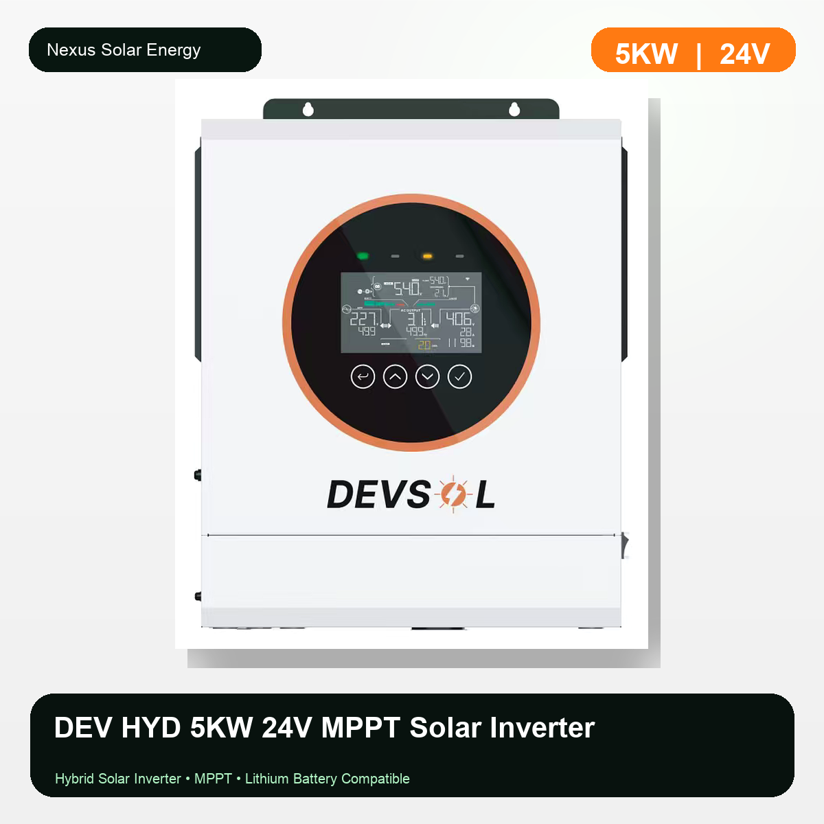
For a current 24V model, see the DEV HYD 5kW product. Compare other hybrid inverter capacities when the battery architecture or load is different.
Nexus Solar Energy and Devsol assemble inverter products in India and provide local support routes. Deepak Chaudhary, CEO and CMD of Nexus Solar Energy, supplies the practical technical inputs behind the examples and presents the linked public demonstrations. Visit his official profile or contact the product team with the exact bank and load details for a suitable configuration.